Video Walkthrough
MOES Star Grand Matter Smart Large Panel Switch, official MOES channel. Click the preview to play.
Before You Start
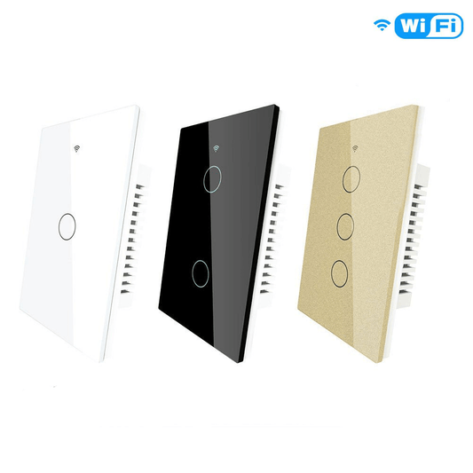
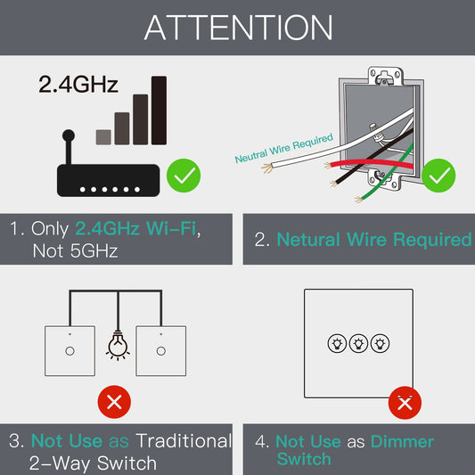
This switch replaces a standard single-pole wall switch and requires a neutral wire in the wall box. It is a full-touch panel: the whole surface is the button, and it is wired like a conventional switch, with line in, neutral in, and one switched wire per gang out to the light.
Tools and Materials
- Phillips #2 screwdriver and a small flathead screwdriver for the faceplate
- Non-contact voltage tester and a multimeter
- Wire stripper, wire nuts or lever connectors, electrical tape
- Work light; optional level for a flush fit
Check the Wall Box First
- Neutral wire: Confirm that a neutral bundle (usually white wires joined with a wire nut) is present. Without a neutral, the switch cannot be powered, so choose another location or run a neutral.
- Circuit type: This is a single-pole switch. In a 3-way circuit (two switches controlling one light), a dedicated 3-way model is required.
- Box depth: Test-fit the module before terminating wires. The body needs clearance behind the panel, and the wiring must fold flat.

Safety
Electric shock can cause serious injury or death. If any part of this procedure is unclear, stop and call a qualified electrician.
Switch the lighting circuit off at the breaker, not just at the switch.
Have a qualified electrician perform wiring work. Before touching or adjusting any conductor or terminal, turn off all circuits supplying the box and verify that all conductors are de-energized. Any testing that requires power must be performed by a qualified electrician.
- Test every wire in the box with a voltage tester before touching it. More than one circuit can enter the same box.
- Never work on a switch with the panel removed and the breaker on.
- Do not exceed 10 A per gang or 10 A in total. At 120 V, that is 1,200 W total; the 2,200 W rating applies at 220–240 V.
- Do not use the switch to dim lamps, control fan speed, or switch loads with a high inrush current beyond its rating.
Identify the Wires
US wiring colors are conventional, not guaranteed. Test before connecting.
| Wire | Typical color | Function | Connects to |
|---|---|---|---|
| Line (hot) | Black | Permanent live from the breaker | L |
| Neutral | White | Return path, required | N |
| Load / lamp | Black, red or blue | Switched live to the light | L1–L4 |
| Ground | Bare copper or green | Safety ground | No terminal on this switch; keep it connected to the box |
If the wall box has a bare copper ground, leave it connected to the box or to the other devices and do not cut it short. This model switches line and neutral and has no ground terminal on the module.
Terminal Layout
Looking at the back of the switch, the terminal block reads N, L4, L3, L2, L1, L from left to right. Line and neutral feed the module; each remaining terminal switches one light.
| Terminal | Wire | Notes |
|---|---|---|
| L | Line (hot) | Permanent live, daisy-chained to the next switch if needed |
| N | Neutral | Required for the module to power up |
| L1 | Load 1 | Gang 1, always used |
| L2 | Load 2 | Gang 2, 2-gang models and above |
| L3 | Load 3 | Gang 3, 3-gang models and above |
| L4 | Load 4 | Gang 4, 4-gang models only |
Gang Mapping
| Model | Gangs | Terminals used |
|---|---|---|
| MWS-SG-US1-WH-MS | 1 | L, N, L1 |
| MWS-SG-US2-WH-MS | 2 | L, N, L1, L2 |
| MWS-SG-US3-WH-MS | 3 | L, N, L1, L2, L3 |
| MWS-SG-US4-WH-MS | 4 | L, N, L1, L2, L3, L4 |
Step-by-Step Installation
Step 1Switch off the breaker.
Turn the lighting circuit off at the panel and confirm the light no longer works.
Step 2Remove the old switch.
Take off the faceplate, unscrew the switch, and pull it clear of the box without letting the wires fall back in.
Step 3Test for voltage.
Verify that the power is off. Use a properly rated voltage tester to check all conductors in the electrical box before touching them. Do not rely solely on the light being off or the breaker position. If any voltage is detected, stop and have a qualified electrician verify the circuit.
Step 4Label the wires.
Mark the line, the neutral and each load wire (L1, L2 and so on) with tape before disconnecting, because the gang order is easy to lose.
Step 5Prepare the conductors.
Strip about 3/8 in (10 mm) of insulation. Straighten solid copper; twist stranded wire tight. Do not nick the copper.
Step 6Connect line and neutral.
Line to L, neutral to N. Tighten each screw firmly and tug the wire to confirm it is clamped.
Step 7Connect the loads.
One load wire per terminal, starting at L1. For a 2-gang switch, use L1 and L2, and so on.
Step 8Fold and mount.
Fold the wires flat, seat the module in the box, and fix it with the supplied screws. Do not trap a conductor against the box edge.
Step 9Fit the panel.
Clip the full-touch panel on from the top, then press around the edges until it sits flush.
Step 10Restore power.
Switch the breaker on. The indicator should light and then flash, ready for pairing.
Pair with Matter
The switch ships in pairing mode. You need a 2.4 GHz Wi-Fi network and a Matter controller, for example, an Apple HomePod or Apple TV, Google Nest Hub (2nd gen), Amazon Echo (4th gen) or a SmartThings hub. The MOES app can also commission the switch directly over Wi-Fi.
- 1. Make sure the indicator is flashing. If it is solid, press and hold the main button for about 6 seconds until it flashes quickly.
- 2. Open the MOES app (or Apple Home / Google Home / Alexa / SmartThings) and choose Add Device.
- 3. Turn on Bluetooth on the phone, because Matter commissioning uses it to find the switch.
- 4. Scan the Matter QR code on the side of the switch or in the manual. Keep this code; it is the device identity.
- 5. Select the 2.4 GHz network and enter the password. Do not use a 5 GHz-only SSID or a VPN.
- 6. Name the switch and assign it to a room. Each gang can be named separately so voice control knows which light is meant.
Multi-admin: Open the device settings in the first app, generate a pairing code and add that code in the second ecosystem. One switch can then be controlled from Apple Home and Google Home at the same time.
Reset and Re-pair
Press and hold the main button for about 6 seconds. The blue indicator flashes quickly after roughly 3 seconds, so release it when it does. The switch is now reset and back in pairing mode; re-add it in the app. A reset does not change the wiring.

Troubleshooting
Before inspecting or adjusting wiring, turn off all circuits supplying the box and verify that the conductors are de-energized. Have a qualified electrician carry out wiring checks and any testing that requires power.
| Symptom | Likely cause | What to do |
|---|---|---|
| No indicator, no response | Breaker off, L and N reversed, or a loose terminal | Re-test voltage at L and N; re-tighten both terminals |
| Indicator on but will not pair | Not in pairing mode, Bluetooth off, 5 GHz network | Hold the button for 6 s; enable Bluetooth; join a 2.4 GHz SSID |
| Pairing drops at the last step | Weak signal or VPN active | Move within 5–10 m of the hub, disable the VPN, and retry |
| Lights flicker | Missing neutral, incompatible LED driver, load near the limit | Confirm that N is connected; test with a different lamp; reduce the load |
| One gang does not switch | Load wire on the wrong terminal | Check the L1–L4 mapping against the gang order |
| Works on the panel, offline in the app | Wi-Fi dropped or IP changed | Check the router's 2.4 GHz band and signal; re-pair if needed |
| Switch warm or buzzing | Wiring error, overload, or device fault | Turn off the circuit breaker immediately. Stop using the switch and contact a qualified electrician. |
Need help with setup or product questions? Contact the MOES support team. For wiring work or electrical safety concerns, contact a qualified electrician.
Specifications
| Item | Value |
|---|---|
| Model | WS12SG (SKU MWS-SG-US1-WH-MS to US4-WH-MS) |
| Voltage | 90–250 V AC, 50/60 Hz |
| Max. current | 10 A per gang; 10 A total |
| Max. load | 1,200 W at 120 V; 2,200 W at 220–240 V |
| Wireless | Matter over Wi-Fi, 2.4 GHz (2.412–2.484 GHz) |
| Max. radio power | < +16 dBm |
| Panel | Full-surface touch, tempered glass |
| Neutral | Required |
| Compliance | FCC Part 15 |
Notes for Support
- The 2,200 W figure on the listing applies to 220 to 240 V. On a 120 V US circuit, the same 10 A limit gives 1,200 W. Quote the current, not the wattage, when advising customers.
- This model is single-pole. Customers replacing a 3-way switch need the dedicated 3-way product.
- Wiring colors in the manual are the common US convention; always tell the customer to verify with a tester.
- The Matter QR code is printed on the side of the module and in the manual; customers who discard the faceplate packaging still have it on the device.